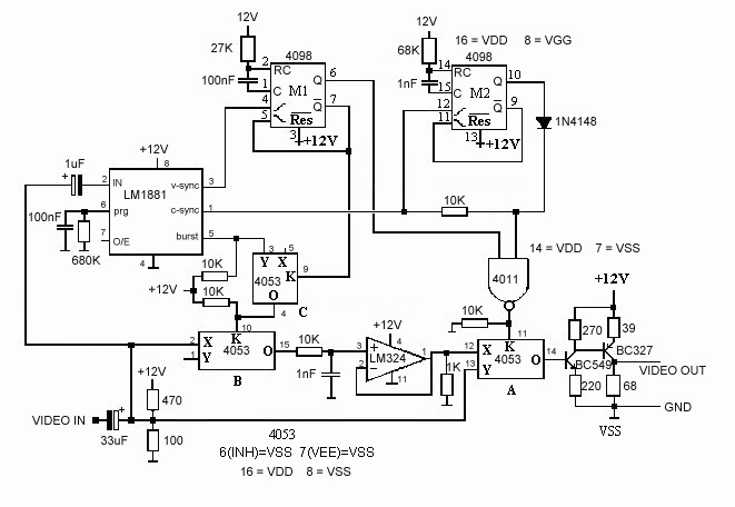
The copy can then be used to make any number of copies, not affected by MV.

Components
What is Macrovision? If you ever tried to copy an original VCR tape you probably couldnt. The copied image is unsynchronised, gets black and it's impossible to view. It's all happening because of Macrovision (MV)!
Technical details
The PAL TV picture is formed of 625 lines in 2 interlaced frames. Only
575 of these lines are visible (287.5 in each frame). The rest are
used for sync, teletext or are simply blank lines. These 25 lines per
frame are necessary for the "dot" to return in the left-upper side of
the picture tube.
MV is an impuls with a variable intensity introduced in the control
part of the lines (after the color burst signal). It can be stronger
or weaker than the sync signal. Modern VCR have an AGC circuit on the
video in line. If the signal is stronger than 1V point-to-point, then
it is "normalized", ie reduced to 1V, keeping the proportion between
the components. So, if the MV signal is 3Volt, the useful signal is
reduced to one third.
TV sets are not affected by these impulses because they lack this
ACG circuitry. Sometimes though, it's possible that some disturbances
occur.
The system was developped by JVC and it's used against illegal
copies of video tapes.
Legal stuff Constructing and selling these devices is legal, but using them might be illegal. You may only copy the video tapes you have bought and only for backup, not for sale, rent or smth else. If you sell the original tape then you have to erase all the copies you made!
The Remover
There are many possibilities to copy protected video tapes. This
schematic has the advantage of stability and low current consumption
due to the CMOS chips used. It can be powered from the pin 8 or the
SCART connector on the back of your VCR.
The copy can then be used to make any number of copies, not affected
by MV.

Components
R1: 27k ohm
R2 : 68k ohm
R3 : 680k ohm
R4-R8 : 10k ohm
R9 : 1k ohm
R10 : 39 ohm
R11 : 270 ohm
R12 : 220 ohm
R13 : 68 ohm
R14 : 470 ohm
R15 : 100 ohm
C1-C2 : 100 nF
C3-C4 : 1 nF
C5 : 1uF
C6 : 33 uF
IC1 : MMC4098
IC2 : LM1881
IC3 : MMC4053
AO : LM324 (or A741, see details)
T1 : BC327
T2 : BC549
Usage
You need 2 VCR: a player and a recorder. You connect them like this:
Player --> MV Remover --> Recorder
You can use SCART or RCA connectors, depending on the VCR you use.
You need a very good 12 volts external supply or you can use pin 8
on the SCART of the player.
Details M324 can be replaced by A741. There are 2 variants, one with 8 pins, the other with 14. The table shows the equivalence between the 2 versions. Pins 1-4 and 5-8 of the 8 pin version overlay exactly on pins 3-6 and 9-12 respectively on the 14 pin version. This means you can use a 14 pin socket.
| PIN | 8pins | 14pins |
| IN - | 2 | 4 |
| IN + | 3 | 5 |
| V- | 4 | 6 |
| OUT | 6 | 10 |
| V+ | 7 | 11 |
The MMC 4098 is contains 2 monstables. The timing is T=0.5*R*C for each gate. T is in uS (microseconds), R in Kohms and C in nF. For the values used in the schematics, M1 has a timing of 21 TV lines while M2 has 34uS (half of a TV line).
LM1881 is a sincroseparator. It outputs a locical pulse each time a sync pulse is detected.
The normal picture passes through and it clears half line after the color burst (the MV impulse).
Contact tvhack@ucsd.com
22 january 2000